Join Our Telegram Community Join Now
| Over charge protection | Balance voltage | ||||||||||||||
| Detect voltage : LifePo4: 3.75±0.05V | Detect voltage: LifePo4: 3.525V | ||||||||||||||
| Protection delay: 1S | Release voltage: LifePo4: 3.525V | ||||||||||||||
| Release voltage: LifePo4: 3.55±0.05V | Balance current: 30±5mA | ||||||||||||||
| Over discharge protection | Over Discharge current protection | ||||||||||||||
| Detect voltage : LifePo4: 2.3±0.05V | Protection delay: 1S | ||||||||||||||
| Protection delay: 1S | Protection release condition: Off load | ||||||||||||||
| Release voltage: LifePo4: 2.7±0.05V | |||||||||||||||
| Short circuit protection | Self Consumption | ||||||||||||||
| Protection condition: Short circuit of external load | Working current: 100~200mA | ||||||||||||||
| Detect delay: 200~500uS (Subject to actual test) | Sleeping current (over-discharge): 0uA | ||||||||||||||
| Release condition: Off load | |||||||||||||||
| Working Temp Charge: -20~55℃; Discharge: -40~70℃ (Customizable) | |||||||||||||||
| Working Temp range: -20~60℃ | Storing Temp range: -40~85℃ | ||||||||||||||
Package includes:
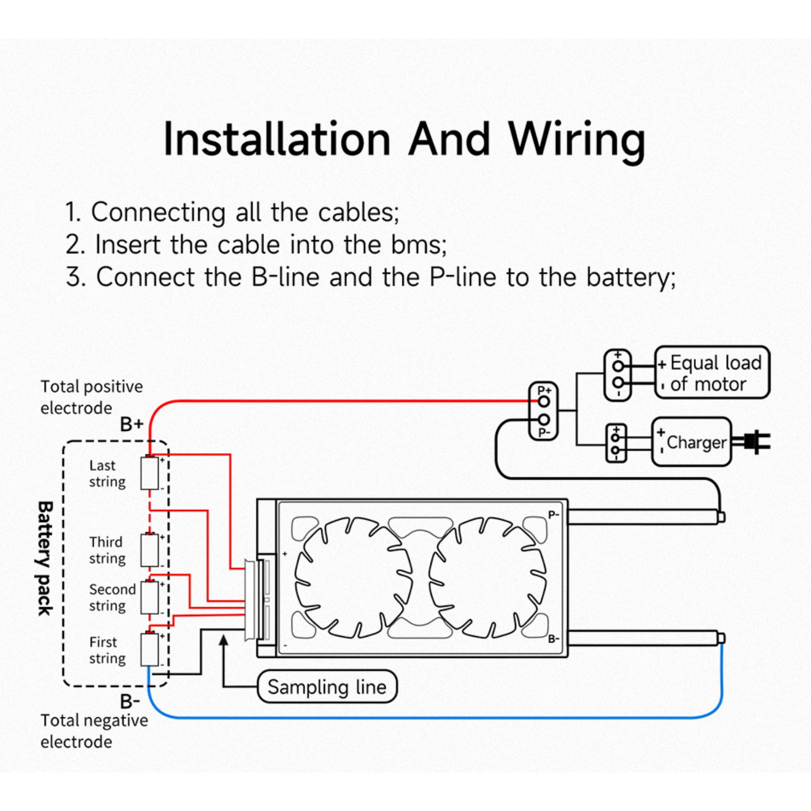
Protective board connection battery wiring:
After the wiring is completed:
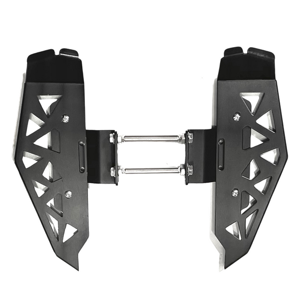
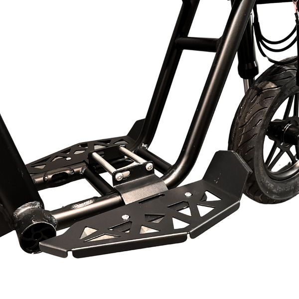
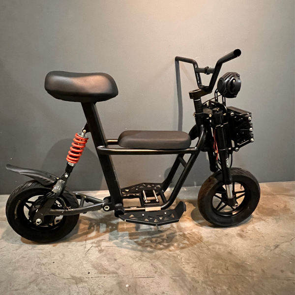
Fiido Foot Sled Foot Slats Fiido Foot Sleds perfect for 2 riders to ride comfortably on...
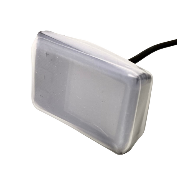
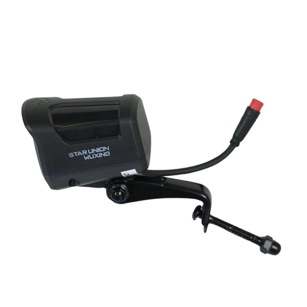
Waterproof LCD Cover for E-bikes Ji Move Ecodrive Rogi Orca Universal waterproof and splashproof cover silicone...
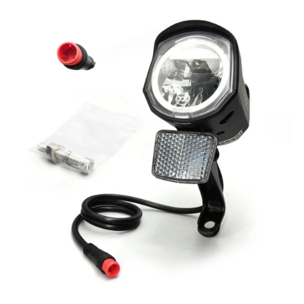
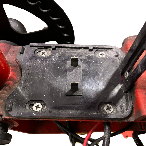
Wuxing Headlight LED 36V/48V/60V/72V for E-Bike E-Scooter Frame mounted LED headlights. Fits on most E-bikes and...
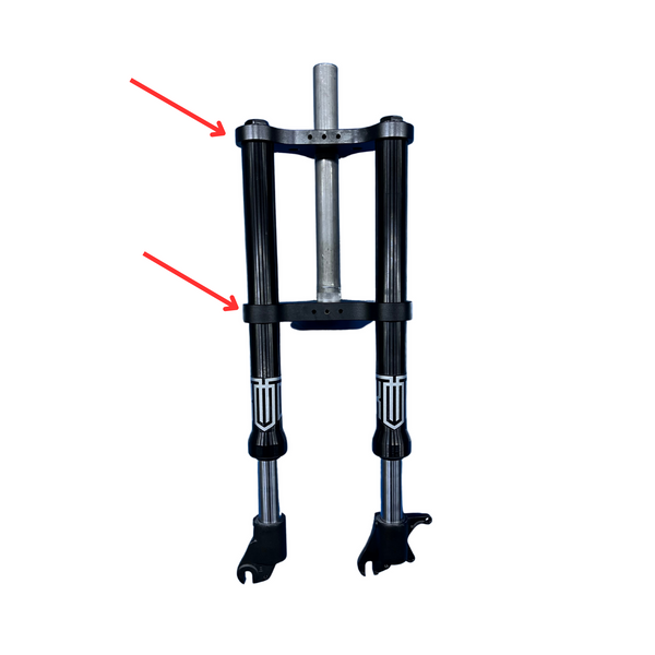

Dual Crown Brackets for Twin Suspension Fork for Fiido Black color only
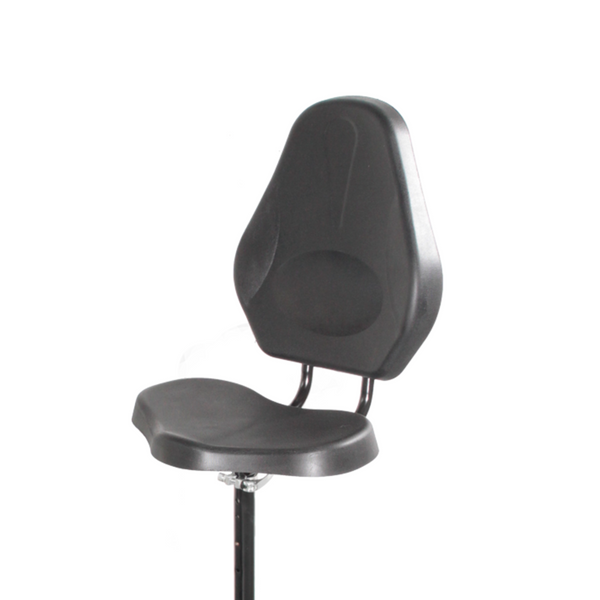
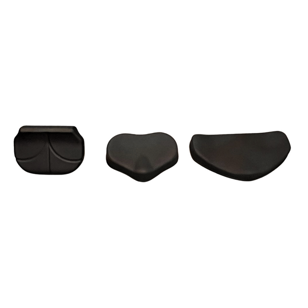
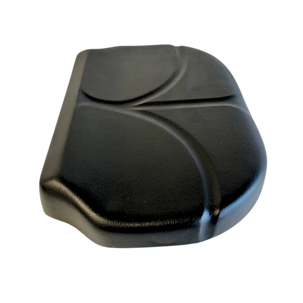
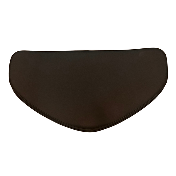
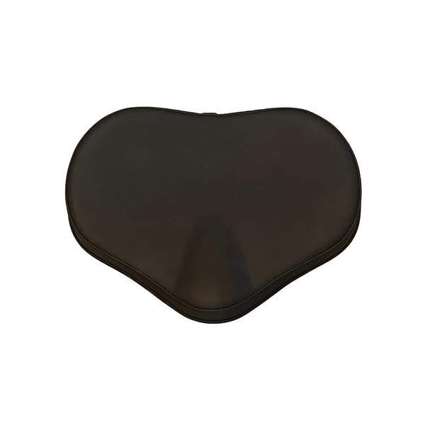
Travelscoot Escape Deluxe Seat Cushion with XL Backrest Foam seat cushion with mounting plate. Small (stock...
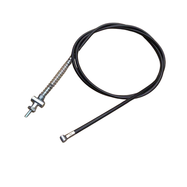
PMA Drum Brake Cable PMA Brake Hose Front and Rear PMA font and rear drum brake...
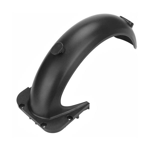
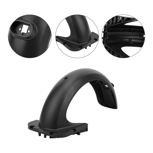
Ninebot Max G30 Rear Fender Rear Mudguard Original Stock rear fender for the Ninebot Segway G30 Max. ...
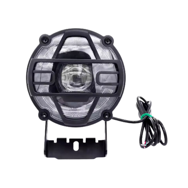
KOTTO Headlight 36V/48V LED with Horn 36V/48V headlight with horn for KOTTO ebike. IP rated waterproofing. Mounting bracket provided....
Orca Battery Base Plate Holder with Rail Orca battery holder and base plate with rail with...
All orders are shipped in 1-2 business days and arrives within 1 week.
Free Shipping on local orders
Experienced Before and After Sales Support